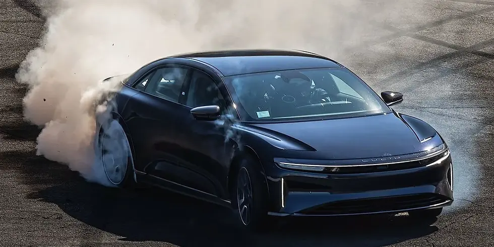
One of my favorite projects so far has been leading the validation testing for a significant cost-savings project for the Sapphire inverter.
The award-winning single drive unit from the Air platform. Since joining the company, I've had a hand in design and releases for upgrades in almost every part of this inverter. For Lucid's Tech-Talk about this system, follow the YouTube link below!

I've taken the role of technical lead for inverter on the Gravity program
One of my favorite projects so far has been leading the validation testing for a significant cost-savings project for the Sapphire inverter.
LUCID MOTORS
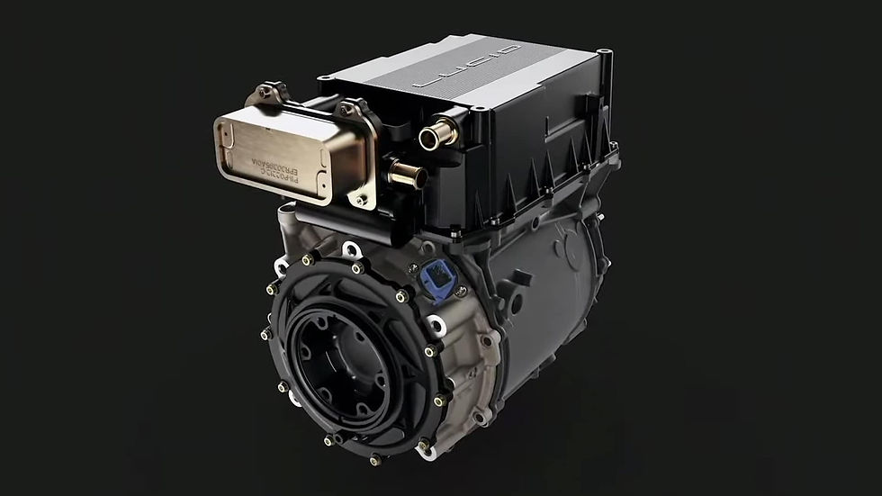
HIGH VOLTAGE INVERTER
2022 - Present
My most recent role is in mechanical design for power electronics on the inverter team at Lucid Motors. Here I've designed heat exchange systems for high-power AC switches, busbars, HV isolation systems, capacitors, coolant interfaces, and more. I've been lucky enough to work on all platforms of Air, Gravity, Sapphire, and next-generation designs.

My job was to decrease mass, increase robustness, and work with design colleagues to create beautiful A-Class interior surfaces that provide the consumer with maximum utility
My job was to decrease mass, increase robustness, and work with design colleagues to create beautiful A-Class interior surfaces that provide the consumer with maximum utility
TESLA MOTORS
INTERIOR SYSTEMS
2021 - 2022
In 2021 I started with the Interiors Team at Tesla Motors in California. I became DRE for over 70 unique parts in the Model S and X platforms, fitting into a sustaining-engineering role.
I worked on design optimizations that decreased mass and weight while improving quality, premium-feel, and robustness. I interfaced daily with manufacturing, NPI, launch, and supply chain teams to maintain timelines and strategize coordinated change cutovers; spending hours on the assembly line to test new parts, theories, and design-for-assembly schemes.
I also worked with design teams like HV/LV harness, packaging/integration, NVH, chassis, and body-in-white to study how upcoming vehicle changes could effect each system. I ran studies on cost-of-cutover based on tool life, and coordinated with suppliers from across the globe to bring upgraded parts into production on strict program timelines.
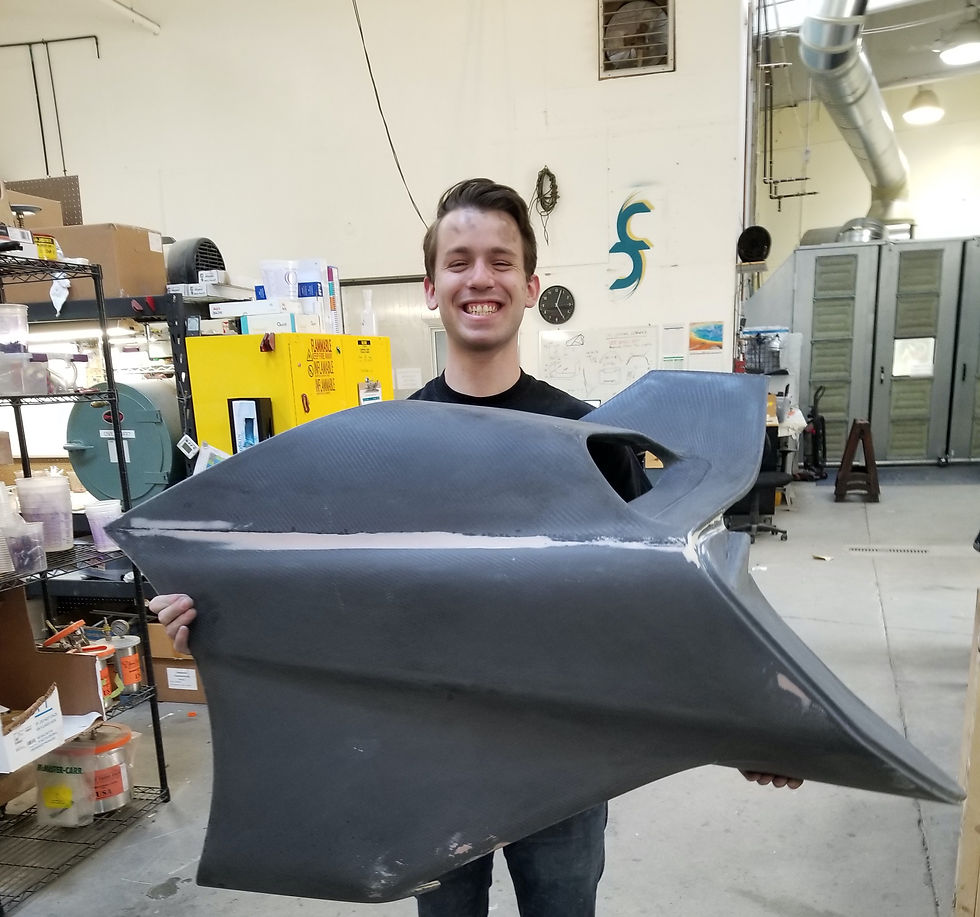
Here I'm holding the right-hand quarter panel of the SSC Tuatara that I layed-up. This was arguably the most complex part that the team had ever completed, and it included structural bracing at key locations to ensure proper rigidity.

Here I'm holding the right-hand quarter panel of the SSC Tuatara that I layed-up. This was arguably the most complex part that the team had ever completed, and it included structural bracing at key locations to ensure proper rigidity.
COMMON FIBERS
TIER-1 EXPERIENCE
2019
In the summer of 2019, I interned with Common Fibers, a composite manufacturing company based in Seattle, WA. During my time there I helped produce body panels of the SSC Tuatara, which has been competing for the title of "World's Fastest Production Car". I also ran 3- and 4-axis CNC machines, developed layup strategies, and wrote specification sheets to help hone production processes to OEM standards.

Exploded rendering of the wireless charging module. Because the units are integrated into the seats, direct access was off the table. My team devised two testers that any technician could use, without disassembling the seat.
Exploded rendering of the wireless charging module. Because the units are integrated into the seats, direct access was off the table. My team devised two testers that any technician could use, without disassembling the seat.
ASTRONICS AES
WIRELESS CHARGER TESTER
2018
In 2018 I Lead the mechanical engineering intern team that designed, built, and validated prototypes for two test devices for the company's new cabin wireless charger. The team was given two desired outcomes, with very open-ended engineering requirements. We ran trade studies on parts, considered high-scale manufacturing cost and sourcing, and ease-of use from a customer standpoint before designing, building, and validating our designs. Our project was the second in program history to complete working prototypes by the end of the intern's summer period.
The first prototype was a Go/No-Go tester that would allow technicians to quickly verify charging capability in a unit in the field. This consisted of a simple and extremely reliable qi-coil circuit and LED indicator in an injection-moldable housing that was designed to resemble a key-card for a familiar user experience. Iterative 3D printed prototypes were used to develop a simple clamshell chassis that withstood liquid and heavy drop testing. I also researched and designed a snap-fitting closure to simplify the parts-list and manufacturing procedure.
The second prototype was a handheld full-cycle power tester designed to run the wireless chargers through the entire range of their power output capabilities, from 5W to 15W. The team used a series of MOSFETs connected to a microcontroller, with a programmed test cycle that hit each power benchmark by using the resistive ranges of the transistors.
This project was a challenge because I had to find a way for 15W of heat energy to safely and continuously dissipate out of 4 TO-220 component housings in a handheld device. The team ended up using a free-convection system with a single large heat-sink to absorb and dissipate the thermal energy of several test-cycles, pausing testing over a 10 minute cool-down period if needed. Inlet and outlet vents were strategically placed at the top and bottom edges of the housing to encourage more airflow while still allowing for natural handling of the phone-shaped device.
The programmed test cycle had built-in temperature shutoffs, where a red LED would indicate that the internal temperature had reached our defined maximum, and would flash if another test was attempted before the unit cooled below our safe-to-start temperature. I designed the housing to solidly place the heat-sink, TO-92 temperature sensors, TO-220 MOSFETS, charging coil circuit, and microcontroller. This enclosure included 4 plastic screws to securely fasten the housing together into one robust unit, which passed drop testing with flying colors even with the 3D printed prototype.
To design the thermal system, SolidWorks' flow analysis software was used on our assembly, assuming realistic thermal-efficiency in the convective transfer. These results were compared against bench top tests using a FLIR thermal camera, which helped us identify our critical hotspots and therefore the placement of the temperature sensors. The safe touch-temperature for the outside of the housing was chosen to be 50°C, so that was taken into consideration, along with the component maximum temperature ratings to develop a thermal map of our enclosure.
I was responsible for the mechanical engineering schedule and deliverables for both projects, and spearheaded the housing design and full-model thermal analysis using SolidWorks' Surfacing and CFD capabilities for both the Go/No-Go and Power Dissipation models. I reported directly to the project manager, and helped bridge the gap between the mechanical, electrical, and business teams to meet our goals. In the end, we met all robustness, thermal optimization, manufacturability, supply chain, timeline, and budgeting constraints. The project was a ton of fun, and it gave me vital experience in project management, and electrical engineering that I've continued to build.